

Drive of High Voltage DC Contactors in electric and hybrid vehicles (EV and HEV)
2021-08-09
1. Introduction
High voltage contactors, also known as high-voltage relays in the industry, are widely used Electric vehicles (EVs) and hybrid electric vehicles (HEVs). It is an electromechanical switchgear with coils Generate magnetic force to mechanically operate electrical contacts. However, using High voltage contactors represent high-power applications in electric vehicles and hybrid vehicles.
As a key safety device for new energy vehicles, high-voltage contactors have the basic function of withstanding high voltage, load, impact, strong arc extinguishing, and breaking capacity. Appropriate current is applied to the coil to ensure appropriate force drives the contacts for robust operation.
This article briefly introduces the high-voltage contactors in electric vehicles and hybrid vehicles, and introduces several How to drive high-voltage contactors.
2. Contactors Distribution in EVs and HEVs
The battery and the traction inverter are electrically isolated by main contactors when the vehicle is switched off for safety reasons. The main positive contactor is between the positive battery pole and the traction inverter while the main negative contactor is between the negative battery pole and the traction inverter. Both these contactors are required for safety robustness. The pre-charge contactor with a series current-limiting resistor is in parallel with the main positive contactor and used to charge the initially discharged DC link capacitor before closing the main contactors to avoid the high inrush current which might damage the battery, power contactors, and DC link capacitor. The two main contactors and one pre-charge contactor comprise an indispensable configuration for full HEVs.
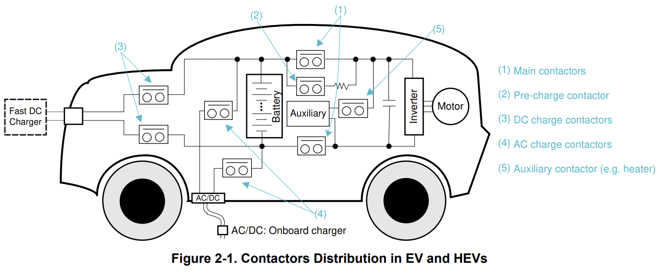
In plug-in HEVs, an additional pair of AC charging contactors are inserted to establish a connection between the traction battery and the on-board charger. The vehicle's on-board charger receives power from the AC charger and converts AC power into DC power to charge the battery.
For battery electric vehicles, insert another pair of DC fast charging contactors to establish a connection between the traction battery and the DC fast charging device. DC fast charging is crucial for long-distance driving and large battery electric vehicle fleets. Auxiliary contactors (such as electric heaters in passenger cabins) are mandatory because internal combustion engines do not have waste heat.
The main contactor, pre charging contactor, and DC charging contactor are mostly located in the battery junction box (or battery disconnect device). The AC charging contactor may be placed in the battery distribution device adjacent to the vehicle charger
3. Power-up Sequence
The traction inverter motor control system must integrate a large set of filter capacitors, commonly referred to as DC link capacitors. Once the main contactor is closed, a huge inrush current will be generated, and the capacitors will be completely discharged. Therefore, the pre charging function is mandatory, and the combination of a contactor and a current limiting resistor to limit the inrush current during power on is the simplest way to achieve pre charging
The process example during the power on process is as follows:
1. After receiving the power on command, close the main negative contactor.
2. Close the pre charging contactor.
3. Close the main positive contactor until the voltage of the DC link capacitor reaches 90% -95% of the battery pack
voltage
4. After the main positive contactor is fully closed, open the pre charging contactor.
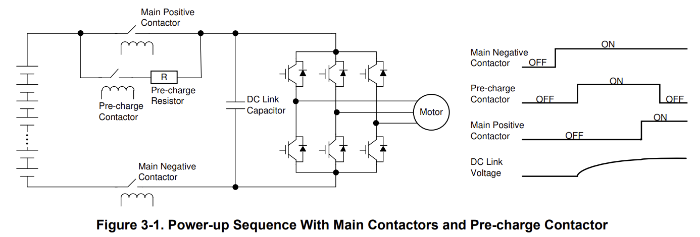
In addition, before closing the contactor, no contacts should get stuck or insulation leakage faults should occur. Contactor status diagnosis and insulation detection must be implemented in system level design
4. Coil Types and Control Requirements
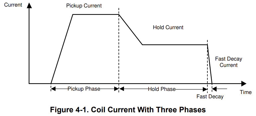
The coil is a key component of a high-voltage contactor because it provides the driving force for closing the contacts. A magnetic field is generated by the current passing through the coil, which attracts the moving core to close the contact, and conversely, opens the contact. Although there are several high-voltage contactor suppliers in the market, such as BSB, TE, Panasonic, the driving current requirements of all contactor coils can be divided into three stages, as shown in Figure 4-1. The first stage is called the pickup stage, and the current should be large enough and maintained for a long enough time to ensure that the contactor closes during this stage. The second stage is the holding stage, where a small current is maintained to effectively close the contactor and keep it closed. The final stage is the rapid decay of current, during which the current drops rapidly and the quenching contacts open quickly. Figure 4-1 shows that the actual current in the three-phase demand pickup and hold stages of the current curve can be PWM signals with maximum and minimum values.
Usually, contactor suppliers provide two types of contactor coils, one with internal components and the other with non energy-saving coils that require external energy conservation. The energy-saving coil integrates the internal economizer with one of several methods, such as dual coil economizer, pulse width voltage feedback modulation, and current feedback pulse width modulation. It only requires two terminals of the power supply coil and the expected current waveform to be generated by the internal energy-saving device itself. The non energy-saving coil that represents this point is just a coil without any internal circuits, requiring external circuits to generate the required current waveform.
5.1 Pulse Width Modulation Current Generation
It is very common in industry to use pulse width modulation to generate the desired current waveform. This duty cycle, which is the ratio of the on time to the signal period, determines the maximum and minimum values to control the frequency of the current applied to the coil.
PWM control typically uses two control methods. The first type is voltage feedback, and the other type is current feedback. Voltage feedback is an open-loop control of current. It measures the supply voltage and sets the duty cycle accordingly. Although it is a low-cost implementation with simple hardware circuits, poor current accuracy, and always leaves a large margin to ensure correct operation. In addition, additional pre calibration work is required to obtain voltage duty cycle diagrams for different contactors.
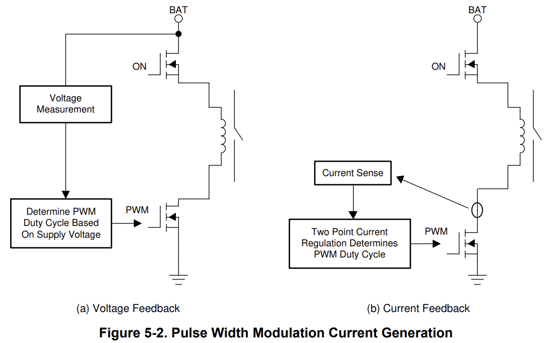
Current feedback is a closed-loop control of current. It continuously measures the coil current and switches directly based on the current. This can ensure high current accuracy and ensure that the coil current is highly consistent with the required current. In addition, voltage duty cycle mapping is no longer required and pre calibration work is saved. However, the cost of this current feedback method may be higher than that of voltage feedback solutions.
5.2 Adjustable Supply Voltage Approach
In the above description, battery voltage is provided to drive the contactor coil. However, the battery voltage is not a fixed value and has a large range during normal operation. This is why dedicated PWM control is introduced to obtain the desired current. Because the current is determined by dividing the applied power supply voltage by the coil resistance, the adjustable power supply voltage of the coil is another option. Figure 5-3 shows the voltage of the adjustable power supply used to drive the contactor coil. The DC/DC converter converts the battery voltage into an adjustable power supply voltage. If the DC/DC converter integration is enabled/disabled, the high-voltage side switch control can be eliminated.
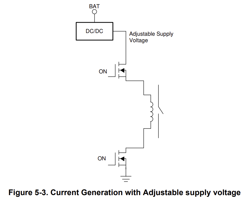
This is more like transferring PWM control from coil driven switches to DC/DC converters. The DC/DC output voltage depends on the coil resistance of the required current. Therefore, during the picking phase and maintaining phase differences. At the same time, it is best to integrate current sensing to check whether the current flows through the coil equal to the desired value.
6. Summary
Contactors are widely used in electric vehicles and HEVs to connect and disconnect power lines. The required current curve generated by the coil of the driving circuit is mandatory to ensure the correct operation of the contactor. Attention should be paid to EMC issues caused by high current and high frequency. In addition, some customers have already used control and diagnostic functions for intelligent contactors with special functions.
Meanwhile, there is a trend towards solid-state switches replacing electromechanical contactors to achieve low noise, high reliability, and long lifespan. Generally speaking, contactors may fail through welding closure, while the failure mode of solid-state switches is mostly open. However, solid-state switches also have some drawbacks. The cost of solid-state switches is currently high, and there is a fixed voltage drop on the output due to internal impedance. In addition, there is leakage current even in OFF mode. This is why it is stipulated that at least electromechanical contactors must be kept at one pole, while solid-state switches are used at the other pole.
How to replace circuit breaker
BSB Electrical Appliances - A Leader in the Field of Hydraulic Electromagnetic Circuit Breakers in China
Related Article
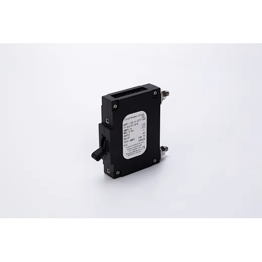
1. Disconnect the power: Be sure to turn off the power before replacing the circuit breaker.
2. Disassemble the old circuit breaker: Use a screwdriver to remove the fixing screws on the old circuit breaker.
3. Test the power supply voltage: use a Voltmeter to test the power supply voltage to ensure that the power supply has been cut off.
4. Remove the wires: Use a screwdriver to remove the wires from the old circuit breaker.
2. Disassemble the old circuit breaker: Use a screwdriver to remove the fixing screws on the old circuit breaker.
3. Test the power supply voltage: use a Voltmeter to test the power supply voltage to ensure that the power supply has been cut off.
4. Remove the wires: Use a screwdriver to remove the wires from the old circuit breaker.
How to replace circuit breaker
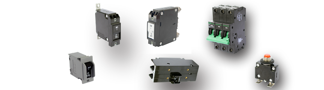
The technical indicators of the product have reached the same level as those of foreign countries; Being the first in the industry to pass EU TUV, VDE, and US UL safety certifications; Becoming the only hydraulic circuit breaker enterprise recognized by the relevant industry...
BSB Electrical Appliances - A Leader in the Field of Hydraulic Electromagnetic Circuit Breakers in China
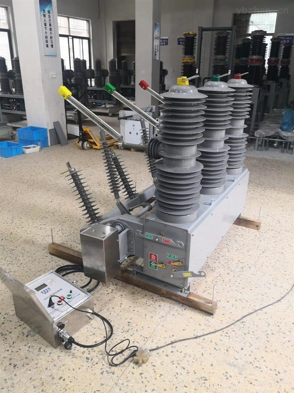
What are the commonly used high-voltage circuit breakers?
What are the commonly used high-voltage circuit breakers? The circuit breaker manufacturer tell you!
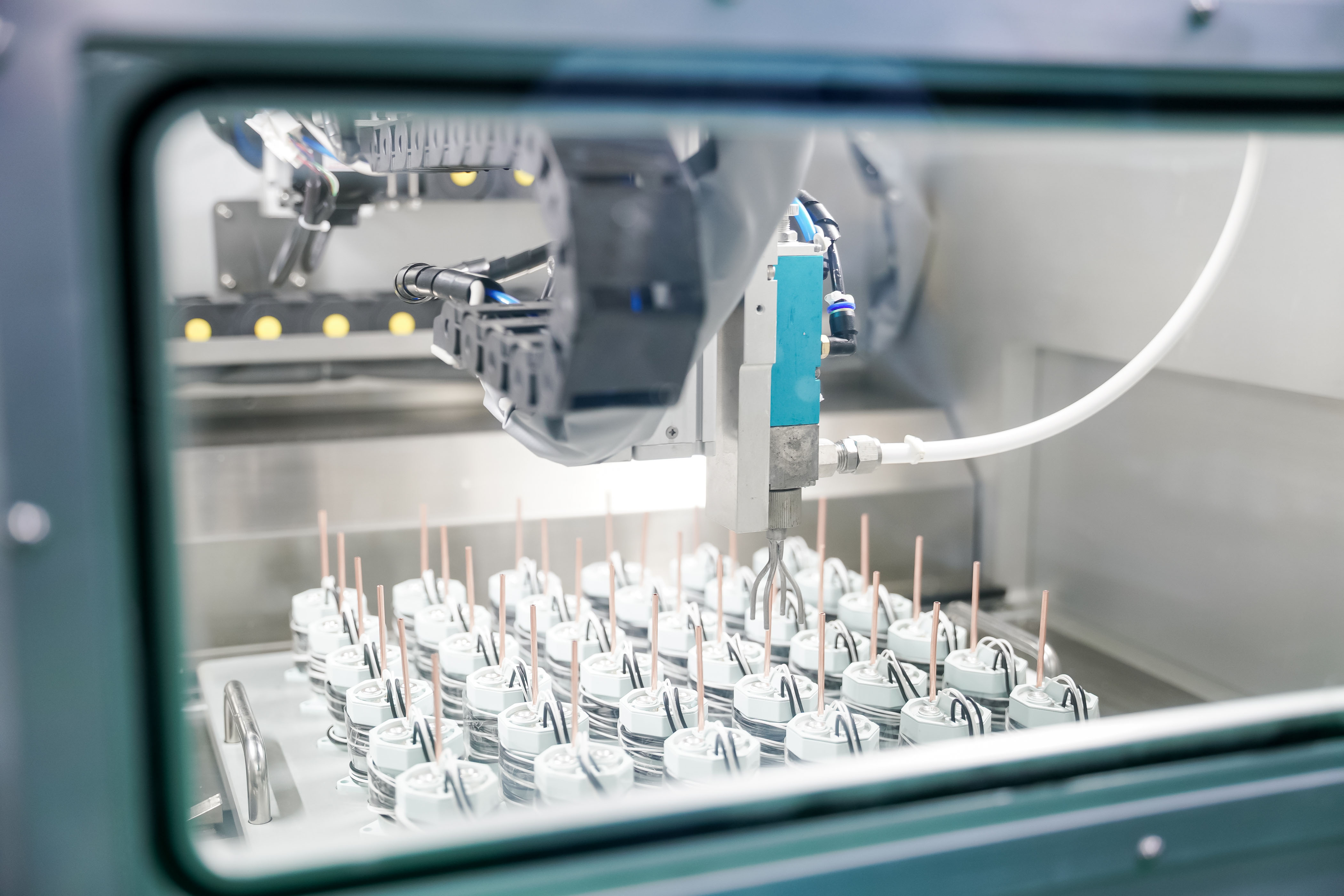
BSB Electrical Appliances Co., Ltd. is an enterprise specializing in the research and development, manufacturing, and sales of low-voltage electrical appliances such as hydraulic circuit breakers and high-voltage DC contactors. The products are widely used in communication equipment, new energy vehicles, charging stations, military markets, and other fields.
How about the BSBC7 series High Voltage DC Contactors?